BFC4013A2B864A9997660DBAC57C94A1.jpg)
.jpg)







Description
-
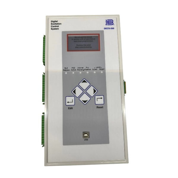
BrandBasler
-
ModelDECS-250-LN1SN1N
-
Product NameDigital Excitation Control System
-
Place of OriginUnited States
-
Customs HS Code85371011
-
Power Supply32Vdc, 63Vdc, 125Vdc
-
Dimensions159 mm × 304.8 mm × 219 mm
-
Weight6.62 kg
-
Operating Temperature-30℃ to +70℃
-
Storage Temperature-40℃ to +85℃
-
Warranty12 month
-
Product Statusnew
DECS-250-LN1SN1N Basler Operation Procedure
1. Pre-Operation Inspection
Cross-check all wiring against electrical schematics, including CT secondary loops, PT voltage sensing cables, field winding connections, DC auxiliary supply and earthing cables.
Ensure CT secondary shorting links are removed; measure insulation resistance of the generator field circuit.
Examine front-panel LEDs for physical damage; verify Ethernet and USB communication ports for BESTCOMSPlus connectivity.
Confirm all interlock and trip circuits are in ready standby status, and all protection parameters have been downloaded and validated.
2. Power-On and Self-Test
Supply auxiliary control power to the DECS-250-LN1SN1N unit.
The controller initiates boot-up and executes the embedded self-test automatically.
Monitor the front LCD and status LEDs. A lit PASS lamp indicates a successful self-test; any abnormality triggers an on-screen fault alarm. Halt commissioning and resolve faults if alarms arise.
Connect a PC to DECS-250 via BESTCOMSPlus, establish communication and read back the device configuration for review.
Confirm the controller is set to OFF / Manual mode prior to generator rotation.
3. Generator Pre-Excitation and Manual Excitation Test
Start the prime mover and accelerate the generator to rated speed.
Switch DECS-250 into Manual mode.
Apply low excitation output incrementally, and track generator terminal voltage through the local HMI or BESTCOMSPlus.
Slowly ramp voltage up to the generator rated value, while checking voltage stability, field current and field voltage.
Decrease excitation output down to zero once manual testing finishes.
4. Auto Mode Commissioning and Auto-Tuning
Switch the regulator to Automatic Voltage Regulation (AVR) mode.
Activate the auto-tuning function within BESTCOMSPlus to compute optimized PID gains for the excitation control loop.
Run auto-tuning following software prompts; maintain the generator at rated speed throughout the tuning procedure.
Upon auto-tuning completion, store the updated PID parameters into the controller non-volatile memory.
Carry out a voltage step test to validate AVR dynamic response and system stability.
5. Synchronization and Grid-Connected Operation
Activate the DECS-250 synchronizing function once generator voltage and frequency stabilize.
The regulator automatically matches generator voltage, frequency and phase angle to the utility grid.
Close the generator circuit breaker when all synchronizing criteria are satisfied.
After paralleling, adjust reactive power or power factor setpoints as needed; continuously monitor VAR output, terminal voltage and field current.
Confirm built-in protection functions (overexcitation, underexcitation, overvoltage, sensing loss) stay enabled under loaded conditions.
6. Normal Operation Monitoring
Track live parameters via the front HMI or BESTCOMSPlus: generator terminal voltage, field voltage, field current, reactive power, operating mode and alarm status.
Regularly review event logs, oscillography records and trend curves to spot abnormal transients.
When alarms appear, acknowledge the alert and locate root causes before modifying any setpoints.
Back up the configuration file to a local PC on a routine basis.
7. Generator De-Loading and Shutdown
Gradually reduce generator reactive load to the minimum level.
Open the generator circuit breaker to disconnect the unit from the grid.
DECS-250 will automatically lower excitation output, and terminal voltage will fall accordingly.
Shut down the prime mover after terminal voltage drops to nearly zero.
Disconnect the DECS-250 auxiliary control power if maintenance is required. Allow full discharge of internal capacitors before accessing internal circuitry.
8. Fault and Emergency Handling
For critical faults including overvoltage, field overcurrent or PT loss, DECS-250 will activate excitation trip and de-excite the generator automatically.
Retrieve fault codes from the front LCD or BESTCOMSPlus event log.
Isolate power supply and inspect wiring, PT/CT assemblies and field circuits before resetting the controller.
Clear alarms only after the fault source has been completely removed.
9. Maintenance
Export and save the configuration file before firmware updates or parameter edits.
Upload new firmware via BESTCOMSPlus; power must NOT be interrupted during the firmware upgrade process.
Re-verify all protection and control logic after every configuration modification.
Conduct periodic visual inspection of terminal blocks and heat dissipation components.

DECS-250-LN1SN1N Basler Application Cases
Case 1: Hydroelectric Plant Excitation Retrofit (Basler Official Reference)
Project overview: A utility company in the Midwestern United States upgraded the outdated excitation controllers of four hydroelectric generators, selecting the DECS-250-LN1SN1N as the new digital excitation regulator.
Challenges: The legacy analog excitation hardware did not support remote monitoring. The power station required unattended operation and seamless integration with the existing Ovation DCS platform.
Solution: DECS-250-LN1SN1N controllers were fitted into the original cabinets. Modbus protocol was deployed to enable data exchange between regulators and the DCS. Embedded event recording and oscillography features streamline fault diagnosis activities.
Result: All four hydroelectric units support remote centralized control. Voltage regulation performance and protection functions passed grid code acceptance tests. Unattended station operation was fully achieved after commissioning.
Case 2: Mobile Gas Turbine Power Unit for Oil & Gas Fracturing Sites
Project overview: Eleven mobile gas turbine generator packages (5.8MW per unit) deployed for remote fracturing operations, each equipped with DECS-250-LN1SN1N.
Challenges: Subject to frequent load variations. The units must operate reliably in both standalone and parallel modes under harsh off-grid field conditions.
Solution: DECS-250-LN1SN1N delivers AVR, VAR regulation and integrated generator protection. It works in tandem with DGC-2020HD to manage genset paralleling and power control. Conformal-coated PCBs ensure stable performance across a broad temperature range.
Result: Terminal voltage remains stable during dynamic load transitions, meeting the power supply reliability requirements of oilfield fracturing equipment.
Case 3: Industrial Cogeneration Retrofit (Waste Heat Recovery Power Plant)
Project overview: Legacy AVR replacement project for a gas turbine generator, adopting the dual-channel DECS-250-LN1SN1N excitation system.
Challenges: The original excitation system suffered from limited spare part availability and poor reliability. Cabinet space was constrained and full cubicle replacement was not feasible. Zero power interruption was mandatory for critical industrial loads.
Solution: Custom backplates were fabricated to mount DECS-250-LN1SN1N inside existing cabinets. A primary/standby dual redundant excitation architecture was configured. Auto PID tuning greatly cuts commissioning duration.
Result: Seamless automatic switchover to the backup channel without power loss upon main controller failure. Dynamic voltage response is enhanced. Protection logic is upgraded together with full waveform recording capability.
Case 4: Water Pumping Station Synchronous Motor Excitation Upgrade
Project overview: A large raw water pumping station with seven units of 3000HP synchronous motors. DECS-250-LN1SN1N serves as the core controller within the SMC-250 synchronous motor excitation system.
Challenges: Limited cabinet footprint. The project targets replacement of ageing brushless excitation controls for large water pump motors.
Solution: DECS-250-LN1SN1N modules were separately mounted on cabinet doors while retaining the original cabinet structure. Integrated excitation limiters and monitoring functions were configured.
Result: Stable excitation control is achieved for large synchronous motors. Following successful trial operation, the customer placed follow-up orders for another 37 units to upgrade additional pumping stations.
Case 5: Swedish Paper Mill 42MW Turbine Generator
Project overview: A 42MW steam turbine generator installed at a paper mill with critical continuous-production loads, fitted with DECS-250-LN1SN1N.
Challenges: Lightning strikes could trigger grid breaker tripping and severe overvoltage, risking paper machine damage and substantial production losses.
Solution: DECS-250-LN1SN1N activates rapid negative field forcing once 180% overvoltage is detected.
Result: The regulator suppresses overvoltage within 900ms. Paper production continues uninterrupted without web breaks, avoiding 14 hours of downtime and €180,000 in economic losses.

FAQ for Basler DECS-250-LN1SN1N
1.Q: What is DECS-250-LN1SN1N?
A: DECS-250-LN1SN1N is Basler digital excitation control system for synchronous generators, used for precise voltage and excitation regulation.
2.Q: What control modes does Basler DECS-250-LN1SN1N support?
A: It supports AVR, FCR, FVR, power factor and VAR control modes to meet different generator operation requirements.
3.Q: Can DECS-250-LN1SN1N be used for generator retrofitting projects?
A: Yes, this model is widely applied in new generator installation and old excitation system upgrade & replacement.
4.Q: What communication and configuration software works with DECS-250-LN1SN1N?
A: It works with BESTlogicPlus and BESTCOMSPlus software for parameter setup, monitoring and offline simulation.
5.Q: Does DECS-250-LN1SN1N have built-in protection functions?
A: Integrated generator protection features are available to safeguard the generator against abnormal operating conditions.
6.Q: What is the lead time for Basler DECS-250-LN1SN1N?
A: Please send us an inquiry for stock status and exact delivery time.



.jpg)